闭环步进伺服系统螺距误差分析及补偿装置的设计(任务书,开题报告,外文翻译,论文说明书22000字,cad图纸5张)
[摘要]数控技术和数控装备是制造工业现代化的重要基础。这个基础是否牢固直接影响到一个国家的经济发展和综合国力,关系到一个国家的战略地位。因此,世界上各工业发达国家均采取重大措施来发展自己的数控技术及其产业。在我国,数控技术与装备的发展亦得到了高度重视,近年来取得了相当大的进步。特别是在通用微机数控领域,以PC平台为基础的国产数控系统,已经走在了世界前列。但是,我国在数控技术研究和产业发展方面亦存在不少问题,特别是在技术创新能力、商品化进程、市场占有率等方面情况尤为突出。在新世纪到来时,如何有效解决这些问题,使我国数控领域沿着可持续发展的道路,从整体上全面迈入世界先进行列,使我们在国际竞争中有举足轻重的地位,将是数控研究开发部门和生产厂家所面临的重要任务。为完成此任务,首先必须确立符合中国国情的发展道路。为此,本文从总体战略和技术路线两个层次及数控系统、功能部件、数控整机等几个具体方面探讨了新世纪的发展途径。
数控技术是机械电子计算机及自动控制等技术有机结合的一门高新技术,已广泛应用于机械制造领域,使制造技术向高速化自动化高精化集成化智能化网络化方向发展,使机械产品在性能上向高精度高效率高性能智能化方向发展,在功能上向小型化轻型化多功能方向发展,在层次上向系统化集合集成化方向发展。专家预言,未来制造业的竞争在很大程度上是数控技术的竞争。
为使本科生研究生学习研究数控技术,使研究者和实验者充分了解和掌握数控环节及数控过程。我们学校依托陕西省数控技术和工业自动化重点实验室,申报了数控试验台研制科研项目。该试验台利用工控机和运动控制器对XYZAB五个坐标进行控制,采用位移检测装置对数控装置执行件的位移进行测量。坐标控制信息检测信息用微机CRT大屏幕显示。整个试验台系统采用开放式模块式结构,研究者可以根据需要对系统进行扩展。可见,本试验具有很强的操作性,是学习数控技术课程必要的实验设备。
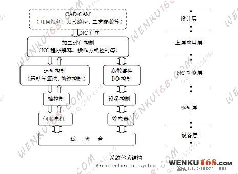
在数控机床中 ,伺服系统是数控机床装置和机床的中间连接环节,是数控系统的重要组成部分。伺服系统接受来自伺服控制器的进给脉冲,经变换和放大转换为机床工作台的位移 ,使工作台跟随指令 脉冲移动 。
数控机床长期运行后 ,传动机构的反向间隙和螺 距误差对定位误差的影响相对突出 ,由于机械磨损 ,使 丝杠螺距误差增大 ,加工精度得不到保证 。而企业里的大多数数控机床都在超性能和超承受能力状况下运转 , 定期检测机床的误差并及时校正反向间隙、螺距等能够切实改善机床精度 , 改善零件加工质量 。因 此 ,企业每隔一定的时间必须进行一次丝杠螺距误差补偿的调整, 这对于提高机床的加工精度非 常 必 要。激光干涉仪对误差的测量精度很高 ,但价格昂贵 ,需要专人操作 ,不适宜在生产现场环境下工作 。步 距规测量制造简单 ,操作方便 ,可以满足大多数数控机床的要求 ,特别适用于我国国情和大批量的数控机床 机电联调的需要。现在的数控系统都采用软件进行螺距补偿 , 将各 点的补偿量存入系统的存储器中 ,数控系统在运行的 过程中可以对各点坐标位置自动进行补偿。分析软件补偿原理 ,掌握具体调整方法 ,正确设定补偿量 ,对 数控机床的使用和维护非常重要。
[关键词]数控系统; PID调节;位置控制器及其补偿装置。
Step-by-step closed cycle servosystem pitch of screw error analysis and compensates the device design
Abstract:The numerical control technology and the numerical control equipment are the factory industry modernization important bases. Does this foundation whether reliable immediate influence to a country's economic development and the comprehensive national strength, relate to a national strategic position. Therefore, in the world the various industrially advanced country takes the important step to develop own numerical control technology and the industry. In our country, the numerical control technology and the equipment development also obtained has taken seriously, in recent years has made the quite big progress. Specially in the general microcomputer numerical control domain, take the PC platform as the foundation domestically produced numerical control system, already walked in the world leader. But, our country also has many problems in the numerical control engineering research and the industrial development aspect, specially in aspect situation outstandinglies and so on technological innovation ability, commercialized advancement, market share. When new century arrival, how do effective addressing these questions, cause our country numerical control domain along the sustainable development path, overall enters into the world advanced ranks comprehensively, enables us to have the pivotal status in the international competition, will be the important task which the numerical control research development department and the Manufacturer face. In order to complete this task, must first establish conforms to the Chinese national condition development path. Therefore, this article from the overall strategy and the technical route two levels and the numerical control system, the functional unit, the numerical control complete machine and so on several concrete aspects has discussed the new century development approach..
The numerical control technology is mechanical technical organic synthesis and so on electronic accounting machine and automatic control high technology and new technologies, has widely applied in the machine manufacture domain, causes the technique of manufacture to develop to the high speed automation high purification integration intellectualization network direction, causes the engineering products to develop in the performance to the high accuracy high efficiency high performance intellectualization direction, develops in the function to the miniaturized light multi-purpose direction, develops in the level to the systematized set integration direction. The expert predicted that in the future the manufacturing industry competition will be the numerical control technology competition to a great extent.
In order to cause the undergraduate student graduate student to study the research numerical control technology, causes the researcher and the laboratory technician understands and grasps the numerical control link and the numerical control process fully. Our school depends on the Shanxi Province numerical control technology and the industrial automation key laboratory, has reported the numerical control test platform development scientific research item. This test platform advantage employing labor controls machine and the movement controller carries on the control to the XYZAB five coordinates, uses the displacement detector set to carry on the survey to the numerical control installment execution displacement. The coordinate control information examination information uses the microcomputer CRT large screen display. The entire test platform system uses the open style module type structure, the researcher may according to need to carry on the expansion to the system. Obviously, this experiment has the very strong operationality, studies the numerical control technology curriculum essential test installation.
In the numerically-controlled machine tool, the server is the numerically-controlled machine tool installment and engine bed's zonula adherens link, is the numerical control system's important component. The server accepts from the servo controller's to feed pulse, transforms after the transformation and the enlargement into platen's displacement, causes the work table to follow the command pulse migration.
After numerically-controlled machine tool long-term movement, transmission system's reverse gap and the pitch error are relatively prominent to position error's influence, because the machinery wears, causes the guide screw pitch error to increase, the working accuracy cannot obtain the guarantee. But in enterprise's majority numerically-controlled machine tool revolves in the ultra performance and under the ultra bearing capacity condition, examines engine bed's error and the prompt adjustment reverse gap, the pitch regularly and so on can improve the engine bed precision earnestly, the improvement components processing quality. Therefore, the enterprise must carry on a time guide screw pitch error compensation once in a while the adjustment, this regarding increases engine bed's working accuracy to be essential. The laser interferometer is very high to error's measuring accuracy, but the price is expensive, needs the specialist to operate, is not suitable in produces under the scene environment to work. The step pitch gauging quantity manufacture is simple, the ease of operation, may satisfy the majority numerically-controlled machine tool's request, is suitable specially for our country national condition and the mass numerically-controlled machine tool mechanical and electrical jointing shake down testing need. Present's numerical control system uses the software to carry on the pitch compensation, stores in system's memory each spot compensation quantity, the numerical control system may carry on the compensation automatically in the movement process to each coordinate position. The analysis software compensation principle, masters the concrete regulation means that establishes the compensation quantity correctly, and maintains to numerically-controlled machine tool's use is important.
Key words:CNC System;PID regulator;Position controller and the compensation device
毕业论文设计的内容要求
根据位置伺服系统在机床上的应用,研究位置伺服系统的结构特点,位置伺服系统的误差对机床加工精度影响。本课题利用机械学院数控试验台,通过光栅传感器测量位置误差,研究影响位置伺服系统误差的因素,用MATLAB软件分析误差分布,找出误差与运动之间的规律,设计位置控制器以及误差补偿装置,使位置系统的运动精度达到要求。
具体任务如下:
(1) 了解本课题目前有关情况,完成楷体报告和英文翻译。
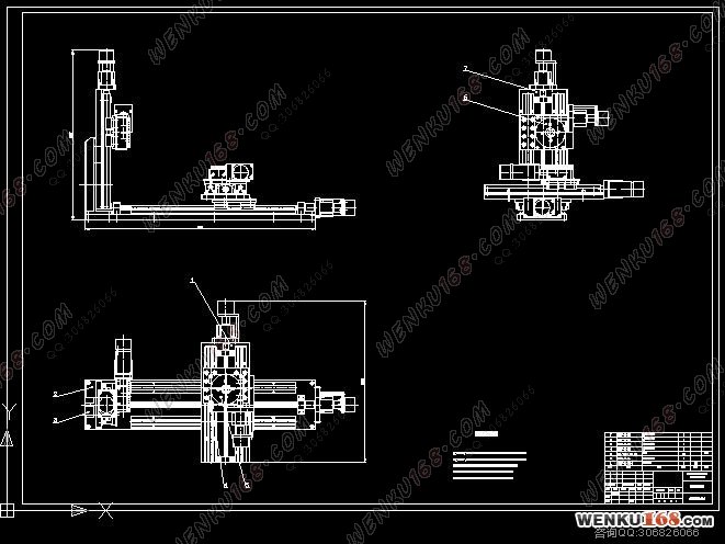
(2) 熟悉机械学院数控试验台的结构和控制系统,绘制数控试验台结构图和控制系统原理图各1张,A0。
(3) 测量螺距误差,找出误差规律。绘制误差分布图1张,A3。
(4) 设计及误差补偿装置,绘制补偿装置图1张,A1。
(5) 编写设计说明书1份,格式和字数满足学院要求。
总体介绍
2.1 主要技术参数
系统达到的技术指标为:脉冲当量0.01mm,多坐标联动控制,行程400mm,最大移动速度2m/min。螺距P=5mm。
确定Z向行程400mm,X、Y向行程200mm;B、C两个转动轴每脉冲转角不大于5分。
Z向采用光栅测量位移,分辨率为0.05mm;X、Y、Z、B、C向电机轴上装编码器,分辨率不大于5分。
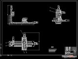
2.2 总体布局
试验台总体布局如图1.1所示。
2.3 控制形式
X、Y、B、C向采用半闭环控制;Z向即可采用闭环控制,也可采用半闭环控制。
2.4 数控装置
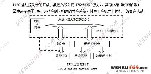
数控装置采用工控机(IPC)+运动控制器(PMAC)
目录
1 绪论 2
1.1数控技术的发展现状和发展趋势 2
1.2毕业论文设计的内容要求 3
2 总体介绍 4
2.1 主要技术参数 4
2.2 总体布局 4
2.3 控制形式 4
2.4 数控装置 4
3 机械部分介绍 5
3.1 滑台 5
3.1.1 导轨 5
3.1.2 丝杠 6
3.1.3 电机 8
3.2 转台 8
3.2.1转台电机 8
3.3 检测元件 9
3.3.1 光栅 9
3.3.2 编码器 9
4 通用运动控制器控制系统的介绍 10
4.1 运动控制器概述 11
4.1.1 运动控制器的构成 11
4.1.2 运动控制器的特点 12
4.1.3通用运动控制技术及运动控制器的发展 13
4.2 PMAC运动控制卡 16
4.2.1 PMAC运动控制卡介绍 16
4.2.2 PMAC运动控制卡应用 17
5基于PMAC运动控制卡构建数控系统 18
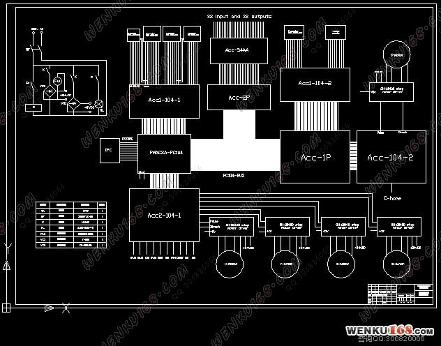
5.1系统硬件组成 18
5.1.1 工控机(IPC) 19
5.1.2 PMAC2A-PC104运动控制卡组 20
5.1.3 I/O板 20
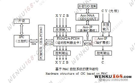
5.1.4 硬件控制系统的结构 21
5.2 系统软件结构 21
5.2.1 概述 21
5.2.2 系统控制软件 22
6数控技术试验台 25
6.1 数控技术试验台总体结构 25
6.2 机械本体 25
6.3 伺服驱动系统 27
6.4 反馈检测装置 28
7 数控技术试验台螺距误差试验 30
7.1 试验台螺距误差补偿 30
7.2螺距误差补偿原因 30
7.3螺距误差的补偿原理 30
7.4螺距误差测量实验步骤 35
致 谢 37
参考文献 38
附录 41
|