VVT-i泄漏量检测台结构设计(含任务书,开题报告,外文翻译,毕业论文说明书20000字,进度检查表,CAD图纸4张)
摘要
随着科学技术的不断进步,汽车的数量也不断增长,人们对于汽车发动机的性能的要求也越来越高。但国内对于汽车领域的研究有限,技术还不够成熟,大部分都是引进国外的先进技术,这导致国内广大的市场为外国人提供无限商机。日本的丰田VVT-i发动机在众多发动机中脱颖而出,近年来为日本鼓足了腰包。所以要在激烈的市场竞争中适应环境变化,加强对新技术的研究迫在眉睫。
泄漏量检测作为完善发动机的一道重要工序,也被越来越多的人研究。检测发动机正常工况下的泄漏情况有助于发现发动机存在的问题和不足,然后加以改进,保证每个出厂的发动机都具有良好的性能。提高产品的质量的同时也提高了产品的美誉,为产品打出了招牌。
本文从结构设计出发,应用已学的知识和实践经验,结合VVT-i发动机的特点,对泄漏量检测台的结构设计进行研究。涉及到检测台的结构设计、液压系统设计、油箱的设计。结构设计又包括钢架设计、工作台面组成和各部分材料选取;液压系统设计包括液压动力部分设计和控制部分设计;油箱的设计包含了油箱构造和容量设计以及辅助元器件的选取。从而确定检测台的整体设计和未来发展趋势,为国内汽车行业走出一条新的致富之路。
关键词:发动机;测漏技术;结构设计;液压
Abstract
With the development of science and technology, the number of cars is increasing; people on the performance of automotive engine are increasingly high requirements. But for the domestic automobile research Co, technology is not mature enough. Most of them are the introduction of foreign advanced technology. This led to the majority of domestic market to provide unlimited business opportunities for foreigners. Japan’s Toyota engine VVT-I talent showing itself among the engine. In recent years, as the Japanese took money. So you want to adapt to environmental changes in the fierce competition in the market, strengthen the research on the new technology of the imminent.
Leakage detection is an important step to improve the engine, has been more and more research. Leakage detection engine under normal conditions is helpful to find the engine problems and shortcomings, and then be improved, to ensure that every factory engine has good performance. To improve the quality of products and improve product reputation, making signs for products.
In this paper, starting from the structure design, knowledge and practical experience has been applied science, combined with the characteristics of the engine, conducts the research to the structure design of leakage detection system. Such as test-bed, hydraulic system design and the fuel tank design. The structure design includes the steel frame design, selection of the material composition and working table. Hydraulic system has the part of hydraulic power and control design. The fuel tank designs the selection of structure and capacity design and auxiliary components. In order to determine of the overall design of test bench and the development trend in the future for the domestic automobile industry walk out of a new road to riches.’
Key words: engine; leak detection technology; configuration design; hydraulic pressure
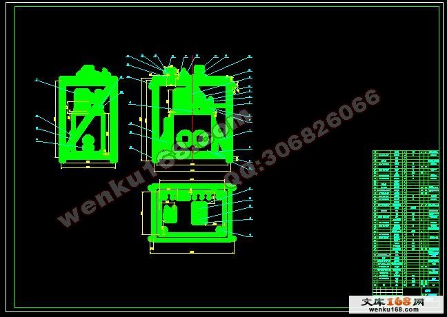
本设计的主要内容是:设计检测可变气门正时系统(VVT-i)泄漏量的试验台架。泄漏试验台架设计内容将包括:钢架结构设计、液压系统设计、控制系统设计。根据汽车发动机上VVT-i系统的特性、整个系统的组成部分、工作环境,采取某些方式来代替其在发动机上的工作,模拟系统和环境,从而达到实验目的。其设计步骤为:
1.观察VVT-i的工况,确定实验台架的组成部分。
2.确定各组成部分的元器件。
3.根据台架的组成部分及元器件,给出台架初步构想图。
4.确定台架部分的结构、详细尺寸、材料及加工方式。
5.对液压部分进行重点分析计算,选择元器件。
6.考虑安全问题,通过设计保护措施保护试验人员安全。
2.2 可变气门正时系统特点
可变正时气门系统这个技术本身并不神奇,但它却具有一定的化腐朽为神奇的功效.其特点是可以确保燃烧稳定,降低油耗,有效改善碳氢化合物和氮氧化合物的排放,同时扩大体积效率,改善燃烧性能。不过跟本田的VTEC相比,由于发动机输出过于平顺,虽然加速并不慢,但给人的加速感并不强,因为扭矩一直保持不变,而在加速过程中阻力不断上升,使得加速的感觉让加速度越来越小。而本田的VTEC由于有着并不平顺的扭力曲线,速度增加时,发动机的扭矩也在不断攀升,而汽车行驶阻力增加的速度远没有发动机扭力增加的速度快使得驾驶起来感觉加速度越来越大,虽然,如果把两台车放在一起拼加速,VTEC不见得是VVT-I的对手,但VTEC能带来更多让人热血沸腾的驾驶乐趣。
目 录
摘要 III
ABSTRACT IV
目 录 V
1 绪论 1
1.1 本课题的研究内容和意义 1
1.2 国内外的发展概况 1
1.3 本课题应达到的要求 2
2 设计内容概述 3
2.1 引言 3
2.2 可变气门正时系统特点 3
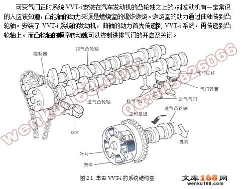
2.2.1 VVT-i的组成 3
2.2.2 VVT-i的工作原理 4
2.2.3 运用到汽车发动机上的作用 4
3 试验台架结构设计内容 5
3.1 钢架设计 5
3.1.1 钢架的设计准则及一般要求 5
3.1.2 钢架结构的设计步骤 5
3.1.3 钢架结构的选择 6
3.1.4 确定钢架结构外形 7
3.2 工作台面的组成 7
3.2.1 工装上平板焊接合件 7
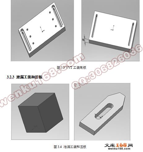
3.2.2 OCV工装支撑板和VVT工装底板 8
3.2.3 泄漏工装和压板 9
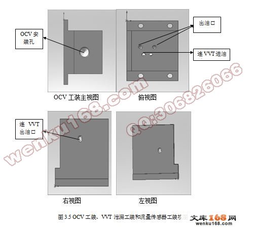
3.2.4 OCV工装、VVT泄漏工装和流量传感器工装 10
3.2.5 防护玻璃罩 12
3.3 各部分材料 12
4 台架的液压系统设计 13
4.1 液压系统的基本组成及设计要求 13
4.1.1 液压系统的基本组成 13
4.1.2 液压系统的设计要求 13
4.2 动力部分设计 13
4.2.1 泵的选型 13
4.2.2 电机的选型 16
4.3 液压系统控制部分 18
4.3.1 液压控制阀的分类 19
4.3.2 液压阀的选择 19
4.3.3 溢流阀的选择 20
4.3.4 减压阀的选择 21
4.3.5 节流阀的选择 22
4.3.6 机油控制阀(OCV)在气门正时系统中的作用 22
4.4 集成阀的介绍 23
4.5 液压系统辅助元器件 24
4.5.1 恒温器的简单介绍 24
4.5.2 蓄能器的简单介绍 24
4.5.3 过滤器的介绍 25
4.5.4 空气滤清器的介绍 25
5 油箱的设计 26
5.1 油箱的构造与设计要点 26
5.2 本液压系统中油箱的设计说明 27
5.2.1 本液压系统中油箱的设计说明 27
5.2.2 油箱的容量与计算 27
5.2.3 油箱的辅助元器件 28
6 三维实体造型 29
6.1 整体台架结构造型 29
6.2 部分组成部分的造型简介 29
6.3 油箱造型的重点介绍 31
7 结论与展望 32
致谢 33
参考文献 34
|