摘要:所设计的四顶顶升系统的主要参数是每只千斤顶高约1000mm,最大行程为400mm,最大载荷为20t。因千斤顶载荷较大,位置精度要求较高,故顶升速度不宜过大,最大顶升速度应控制在60mm/min以内。
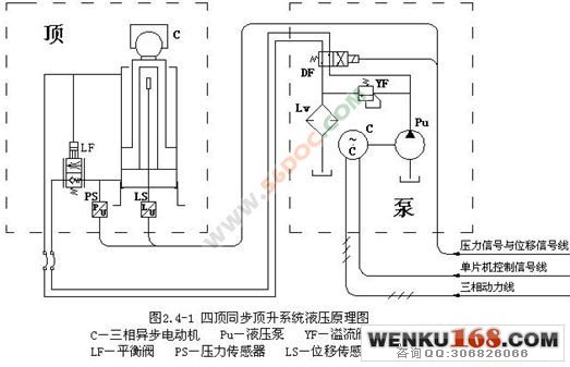
工作原理是,二位四通电磁换向阀的电磁铁的工作状态是由单片机控制的,当换向阀电磁铁通电时,换向阀左位接入系统,油液经电磁换向阀和平衡阀进入油缸下腔,使得千斤顶上升,再从油缸上腔流出,经电磁换向阀和滤油器流回到油箱内,这时平衡阀的作用相当于一个单向阀;反之,当换向阀电磁铁断电时,换向阀右位接入系统,油液经换向阀流入油缸上腔,当上腔压力达到一定值时,平衡阀上位接入系统,这时平衡阀的作用相当于一个节流阀,油液从油缸下腔流出,经平衡阀、电磁换向阀和滤油器流回到油箱。从而实现了千斤顶升降换向功能,并具有过载保护和断电保护的功能。
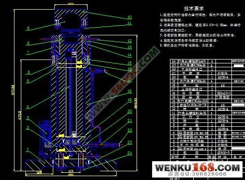
为了适应复杂工作表面的工件,千斤顶的工作台与活塞杆应采用转动连接副相连当顶升系统工作时,液压千斤顶工作台可随工件表面形状进行自由转动调节,所以设计时将活塞杆顶部插入球头,与工作台形成转动副。
由于光栅尺的尺寸较长,将活塞和活塞杆做成中空状来放置光栅。工作时发光元件与光敏元件随活塞作同步运动,光栅尺下端固定在底盖上不动,光源与光栅尺的相对位移量通过读数头转化为数字信号传递给单片机。
关键词: 四顶同步顶升 单片机 光栅
Servo hydraulic jacks
Abstract: Digg this liter four-designed system, the main parameter is the high per jack about 1000mm, the maximum stroke is 400mm, the maximum load of 20t. Jack load due to a larger location with high precision, thus lifting speed should not be too large, the maximum lifting speed should be controlled within the 60mm/min.
Works, the two four-way solenoid valve of the solenoid working state is controlled by the microcontroller, when the solenoid valve energized, the valve Left access system, oil by the solenoid valve and balancing valve into the cylinder under the cavity, so jack up, and from fuel tanks on the cavity flow, flow through solenoid valve and filter tank back in, then the role of balancing valve is equivalent to a one-way valve; the other hand, When the solenoid valve power, the valve access system the right position, oil flows through valve cylinder on the cavity, when the chamber pressure reaches a certain value, the upper balance valve access system, when a balance acts as a throttle valve, the oil flow from the fuel tank under the cavity, by balancing valve, solenoid valve and filter flow back to tank. In order to achieve a lifting jack for the function, and have overload protection and power protection.
In order to adapt to the complex work piece surface, jack the table should be used with the piston rod connected to rotate connections made at work when lifting systems, hydraulic jack table with the surface shape can be adjusted freely rotate, so when the piston rod at the top of the design Insert the ball, and form a rotating table vice
As the size of a long grating, the piston and piston rod to place the grating made of hollow shape. Work light emitting devices with photosensitive elements for synchronous movement with the piston, the bottom grating fixed to the bottom cover fixed, light source and grating by reading the relative displacement of the first into a digital signal is passed to the microcontroller.
Keywords: 4 Synchronous Lift SCM Grating
设计一个由液压驱动,单片机控制,使用PID控制算法的四顶同步顶升系统。
特色:该系统具有位置检测和压力检测功能,可适用于不规则工作表面的工件,并且体积小、承载适中、精度高、结构简单、控制方便,具有很高的实用价值和市场空间。
机械结构与液压传动系统设计
四顶同步顶升系统由千斤顶、超高压泵站、控制系统和操作台四部分组成。
我们所设计的四顶顶升系统的主要参数是每只千斤顶高约1000mm,最大行程为400mm,最大载荷为20t。因千斤顶载荷较大,位置精度要求较高,故顶升速度不宜过大,最大顶升速度应控制在60mm/min以内。
千斤顶的动力系统有液压式、气电式、汽液两用式等,考虑到成本、实用性、使用舒适度等因素,我们最终选用了技术比较成熟的液压系统。
目录 26000字
1. 引言 2
1.1 选题的依据及课题的意义 2
1.2 国内外的研究概况 3
1.3 单片机控制系统的发展概况 4
1.4 PID控制算法的发展概况 5
1.5 设计要求及工作内容 6
1.6 目标、主要特色及工作进度 7
2. 机械结构与液压传动系统设计 7
2.1系统结构分析 7
2.2 千斤顶零部件分析 9
2.3 油缸与螺纹的校验 12
2.3.1油缸的壁厚校验 12
2.3.2 锁母螺纹牙剪切强度校验 13
2.3.3锁母螺纹牙的弯曲强度校验 14
2.4 液压系统分析 14
2.5 液压泵与电动机的选择 15
2.6 超高压泵站简介 16
3 . 单片机控制系统设计 17
3.1 单片机的选用及功能介绍 17
3.2 片外存储器功能简介 18
3.3 显示部分设计 21
3.4 键盘部分设计 25
3.5 交流异步电动机变频调速系统 27
3.5.1 交流异步电动机变频调速原理 28
3.5.2主电路和逆变电路工作原理 28
3.5.3 变频与变压 32
3.6 位移检测部分的设计 38
3.6.1 位移检测传感器的选用 38
3.6.2 光栅位移传感器与单片机的接口设计 40
3.7 位移传感器部分的设计 43
3.7.1 A/D转换器的选择 43
3.7.2 压力传感器与单片机的接口设计 47
4.系统的PID控制算法 48
4.1 PID控制原理 48
4.2 数字PID控制算法 50
4.2.1 位置式PID控制算法 50
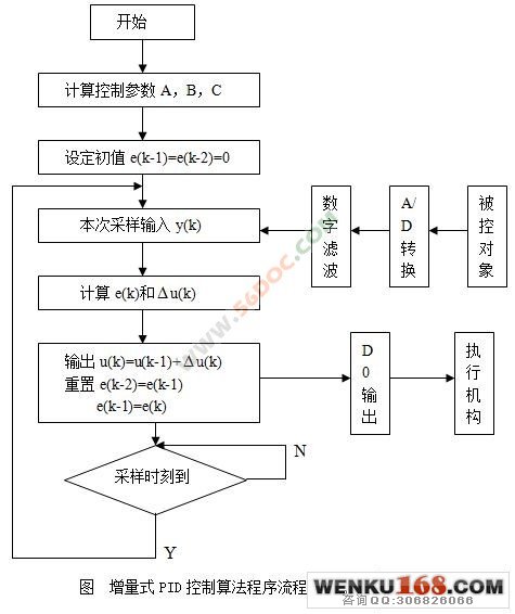
4.2.2 增量式PID控制算法 51
4.3 智能自适应PID控制器 52
5. 系统模拟仿真 57
5.1 SIMULINK概述 58
5.2 SIMULINK的窗口和菜单 58
5.3 用SIMUINK创建模型 60
5.4 用SIMULINK进行系统仿真与分析 61
5.4.1 建立控制系统模型 61
5.4.2 系统模块参数设置与仿真参数设置 62
5.4.3 系统仿真与分析 64
6.结论 67
7.致谢 68
8. 参考文献 68 |